Automatic and seamless connections for brain aneurysm mesh
By Piotr Fröhlich
Earlier this year, we faced a great challenge that consisted of several other, hidden challenges. For our client – BIOMODEX® – we were supposed to, automatically, connect the inflows and outflows of a segmented 3D model of a brain aneurysm [1] to points in a 3D space – and do so seamlessly.
To add on top of that challenge, we only had mesh as an input reference (no indication as to where the endings of the vessel were, where the aneurysm was located, etc.). What is more, we had to follow specific requirements for where such a cutting point can be located in relation to the aneurysm and the 3D points. Let’s also talk about what exactly is the segmented 3D model of a brain aneurysm – firstly, let’s see some visuals, fig. 1. See this mesh? It’s a perfect 3D model, built from a medical image, of someone’s organ (like this aneurysm). In our case, it’s a brain aneurysm with vessels feeding in and out. Since it’s a brain, the mesh uses tiny triangles, with vessels as small as 5 millimetres. To see that in scale, refer to fig. 2. This scale makes it even more difficult due to the small margin of error while we operate in such microscale models where +/- 1 [mm] can be almost 100% of the vessel diameter.
Brain aunerysm. The solution
We divided this solution into several steps that I’ll describe in further paragraphs. We start by calculating the centerlines of the model – this enables us to know several things about the presented mesh, such as diameters along the centerline points. Then we divide the provided mesh into separate branches, so that we are able to establish which part of the mesh is an aneurysm and which part is an ending of the model. Then we proceed to the optimization part of the automatic connection – when we decide which point to choose for cutting the branch and connecting it to the 3D point in space. Lastly, we cut the branches and seamlessly connect them to the 3D points. Besides, this division was also enriched with safety checks. Developing medical devices requires strict checks. Our goal? Minimize human error by automating brain aneurysm branch connections. This ensures optimal results and meets safety standards.
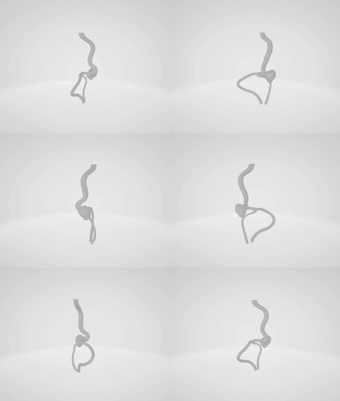
Figure 1
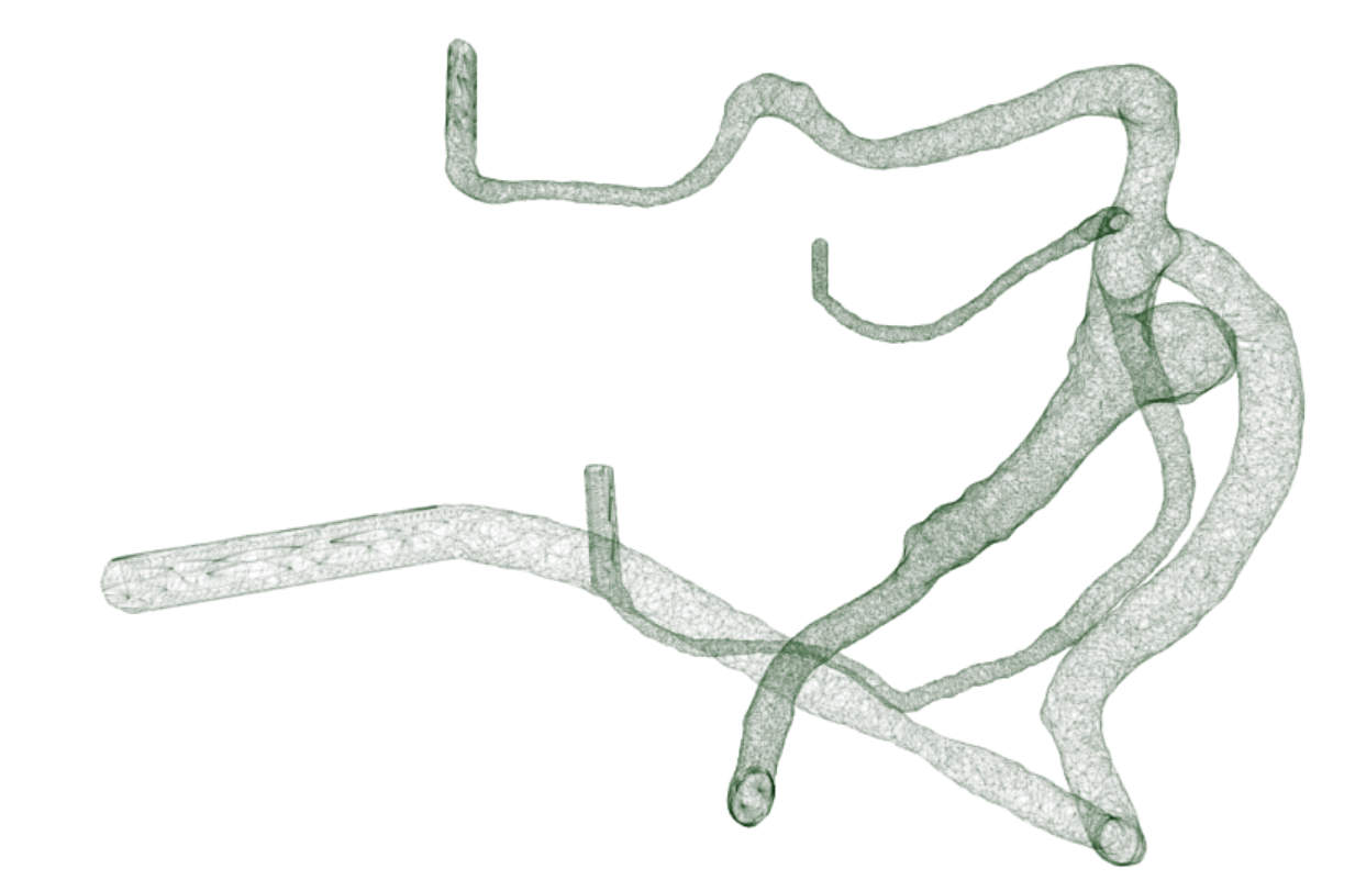
Figure 2: Segmented aneurysm model and a sphere with 5[mm] diameter
To summarize, the steps are:
- Centerlines calculation
- Inflow confirmation
- Splitting into branches
- Calculation of aneurysm location
- Aneurysm confirmation
- Selection of cutting points
- Cutting and connecting the branches in cutting points
Centerlines calculation
Centerlines are a set of points leading from point A to point B going through the center of the model. As you can see in fig. 3, the centerlines calculated for the model incorporate the aneurysm and go through the middle of all the branches that go in and out of the aneurysm. Additionally, centerlines help understand the model’s structure. They tell us the vessel diameter at each point along the centerline.
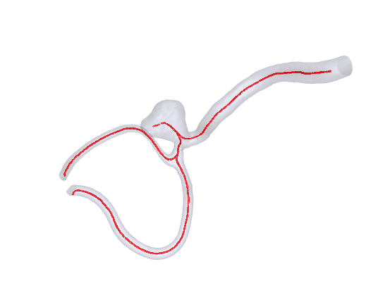
Figure 3: Calculated centerlines for the mesh
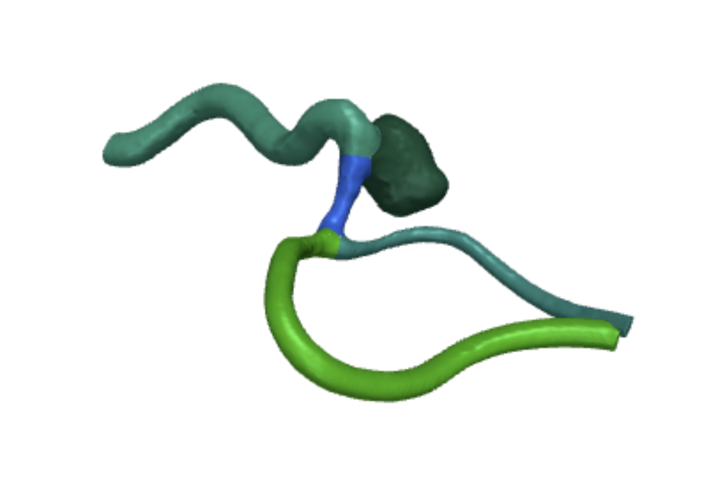
Figure 4: Mesh after splitting into branches
That is a lot of information – we obtain it by utilizing vmtk module, which collects this information by pulling spheres through the mesh. This is actually what we obtain as the branch radius – a maximal radius of an inscribed sphere. Even if we have very small, thin branches, this information is still enough because there is a separate centerline for that small branch. Due to the fact that the vmtk does not provide a stable enough solution, we introduced a set of fallback mechanisms to obtain the centerlines. Upon detecting an incorrect centerline (e.g. consisting only of the first and the last point) we fall back on another algorithm to calculate the centerlines. That algorithm is based on the network extraction and provides more consistent results, with the computation time being the tradeoff. Initially, we tried a raycast algorithm as a quick solution. However, biological complexities in the meshes made it inaccurate. While it was the fastest option, we needed better precision.
First safety check
After the initial centerline calculation, a safety check must be introduced to confirm that the inflow was estimated in the correct place. This is one of two human interactions that our algorithm requires (both are optional and are introduced solely to increase safety).
Branch splitting
Centerlines alone can’t pinpoint the aneurysm. Since it’s a short, thick branch, we use these features to estimate its location. To calculate aneurysm placement, we need to split the mesh and centerlines into branches. We do this by grouping them: each group is a mesh section between crossroads (like Fig. 4). Focus on the blue section in Fig. 4. It represents the mesh between the aneurysm and the branching vessels. The aneurysm itself is a separate group (dark green, top right).
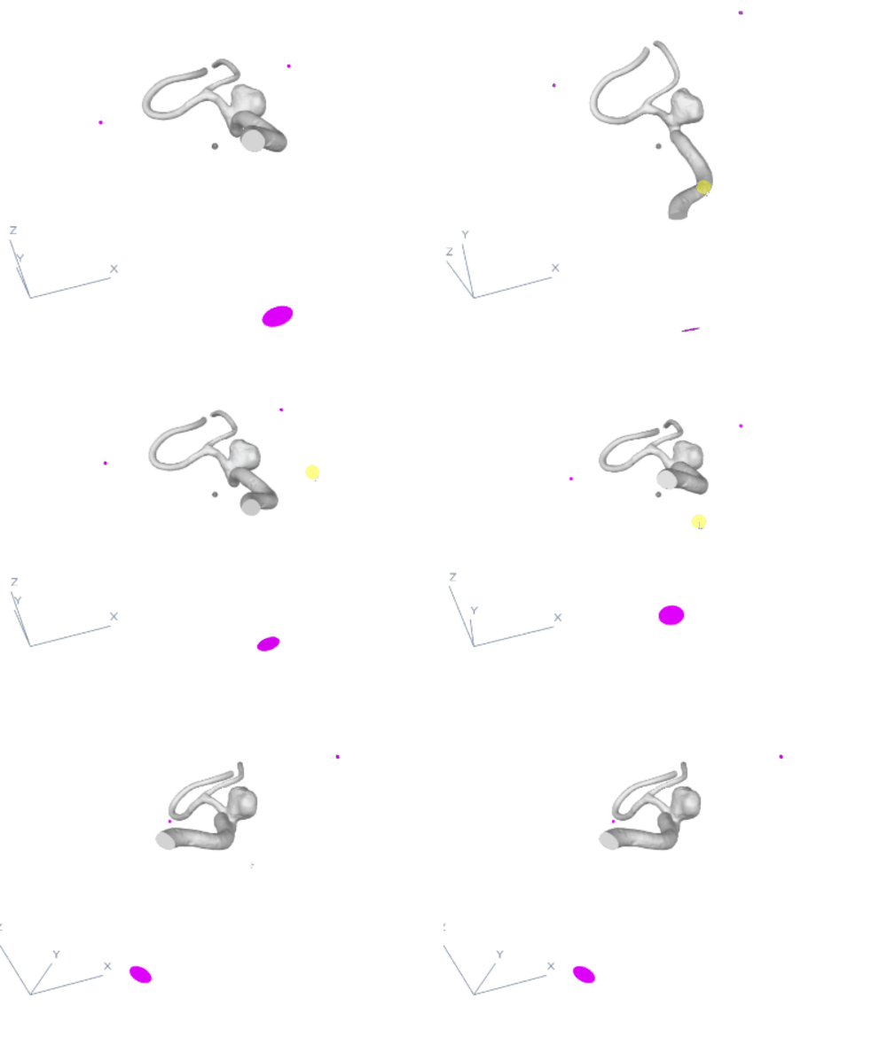
Figure 5
Calculation of brain aneurysm location
With the mesh already split into branches, we can now identify the aneurysm. We achieve this by using aneurysm features: the thickest and shortest branch is flagged. However, if no branch meets this threshold (short and thick), we don’t estimate an aneurysm. What’s more, this prevents us from mistaking a regular branch for the aneurysm.
Second safety check
Lastly, after the estimation of brain aneurysm placement, a second safety check must be introduced. We must confirm that the aneurysm is indeed in the correct place.
Selection of cutting points
Up to this point, we have calculated where the endings of the model are (with the division into inflow and the rest). We also know which one of the branches are not in-between any crossroads. And of course where the aneurysm is. We now have to calculate the optimal way of connecting the endings to the points in 3D space in such a way that they are not in collision with the model, are far enough from the aneurysm and are as short as possible. Additionally, the connection cannot intersect with itself. As we see in fig. 5, the points in 3D space (in pink) are located as shown on the animation. The algorithm will now try to select a point on each of the branches with the endings to create an optimal tube connection between this selected point and the point in 3D space. It will do so by iterating over N points on the branch and calculating the tube (with all the restrictions and optimizations) for all of those points and selecting the best options for all the endings. This way, we know that the created tubes are the best possible tubes that can be created in this setting.
Cutting and connecting the branches in cutting points
Having the cutting points calculated for the optimal tubes, we cut the mesh using planes that are perpendicular to the tangent vector created by consecutive points of the centerline in the cutting point. After the branches were cut in the correct places, we used our own algorithm or connection sweeping (that will be described in another article) to create a seamless connection between the shape of the branch and the created circular tube. The result can be observed in fig. 6.
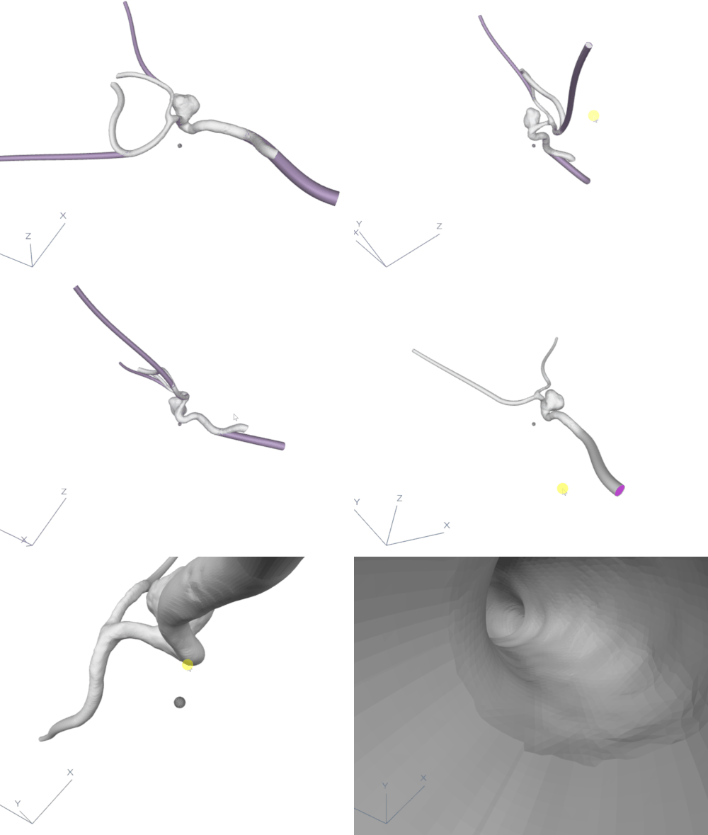
Figure 6
Conclusion: automatic and seamless connections for brain aneurysm mesh
As we described in the article, we were able to solve the problem at hand. Our algorithm can generate seamless tube connections between the segmented 3D model of a brain aneurysm and the points in 3D space. Additionally, the utilization of heuristics and algorithms enabled us to provide a way to lower man-made mistakes and profoundly increase the speed of creating such connections. Moreover, overcoming these challenges made us a stronger team. We honed our skills in complex problem-solving, mesh operations, and risk management. In other words, these hurdles turned us into better problem-solvers and mesh experts, all while improving our ability to manage risks.
See the previous post: Our contribution to ITK-SNAP open-source software.