Generating 3D printable mesh models of brain arteries
By Piotr Mokry
The previous articles described some of the challenges we faced in processing 3D meshes of brain aneurysm models. These articles focused on creating the best possible way (considering some factors) to connect a vessel model to a specific point in space. The ultimate goal? A printable 3D model.
As I have said, we previously explained how to find the best starting points for connections (based on a cost function). Next, we create a smooth target mesh along the connection. This mesh starts circular and transforms to match the original anatomy’s cross-section.
This article tackles the final step: building walls around the 3D model. These walls have a set thickness and maintain the original shape. The goal is to make the model printable while keeping it strong. This process is automated (except for setting wall thickness) and creates a specific shape for use in a flow simulator.
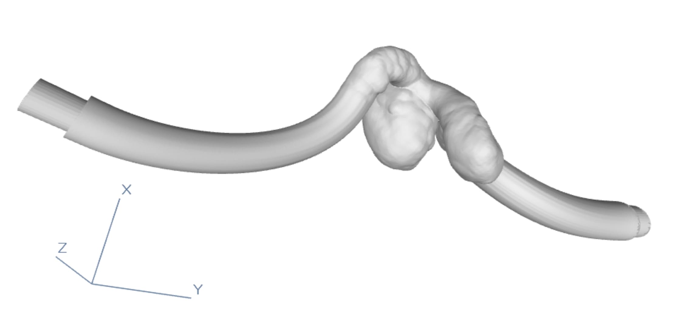
[Im. 1 3D model with generated offset]
Preparing the Model for Printing
The main objective of this tool is to create printable spatial mesh based on a pre-set 3D model (mesh). But not only. It also defined inlet locations (coordinates and direction) for the simulator. As a whole, the preparation of such 3D printable models consisted of the following steps:
- Model cleaning up by removing unnecessary branches with a safety margin.
- Determination of the locations in the space where the vessel is to be connected.
- Generation of pipes connecting the model to these locations ensuring the least possible change to the main model.
- Generation of walls.
- Preparation of the ends of the generated model to connect it to the simulator.
The first three steps have already been described in other articles, in this one we will cover the last two.
3D printable models – the last step
The last operation that prepares the 3D printable models is the generation of walls with a pre-set thickness.
In the author’s project, several additional assumptions and constraints were imposed on this step. In general, the process boiled down to the following steps. Firstly, it cut off the closing fragments from the target vessel (it had pre-generated connections, described in the previous articles). Secondly, it generated an iso-surface for a mesh, equidistant from the initial mesh over the entire volume of the vessel. Thirdly, it prepared the end. Functionally, this was to be done by Boolean subtraction of the mesh from the tube representing the connection point. We wanted it to fit as tightly as possible into the element (the applied ring). That step ensured tightness and stable attachment of the element to the target structure.
Finally, the surface, along with the prepared end for the simulator connection, had to be connected to the output model.
Generation of Iso-surfaces
Creating a kind of an envelope (a surface equidistant from the pre-set surface in space) doesn’t seem a difficult process. Even with an analytical description of this surface. However, this step is highly dependent on the properties of this surface (mesh). This surface isn’t described analytically and may have anomalies affecting the process (e.g. small distance between branches of the model).
Automated process
In addition, the process was to be automated and not alter the original model. We wanted to disturb the physical properties of the model as little as possible. To this end, in the first step we created a binary mask with the best possible resolution. A mask based on the pre-set surface mesh (within reason due to limited computational capabilities and time overhead). With this mask, we determined the Euclidean Distance Transform [1]. Or more precisely, the transform applied to the area outside the generated mask. Then an iso-surface in the form of a mesh was created. It had a constant, pre-set distance from the initial vessel over the entire volume. The generated surface may have had some disturbances and places where the distance deviated from the assumed one. Why? For example, the low output resolution of the surface could cause it. To this end, it was tested whether for each vertex of the envelope the original model at a pre-set distance was found. If not, the vertices of the envelope were slightly offset along the gradient (the EDT determined). After slightly smoothing the resulting mesh (Laplacian smoothing), we checked again the distance of the vertices. Depending on whether it obtained the desired accuracy or not, such an offset was made again.
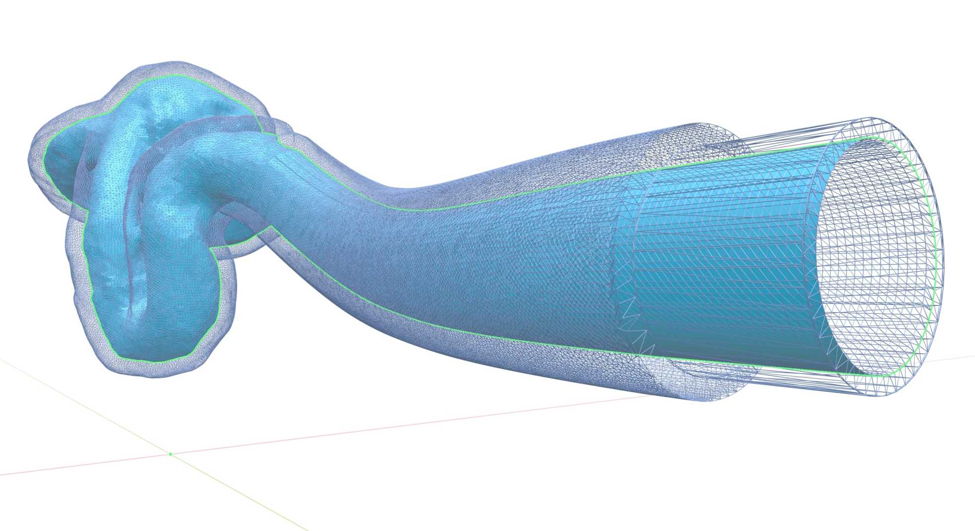
[IM 3D model with transparent offset]
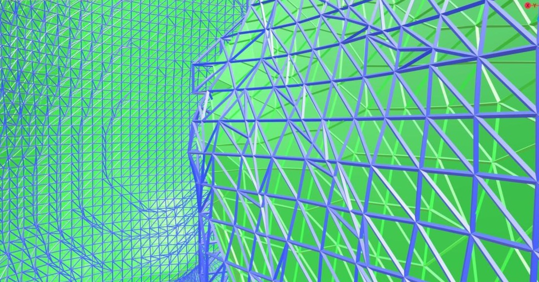
[IM mesh before and after smoothing]
Creation of the outlet
When preparing the aneurysm model, which was eventually to be connected to a kind of simulator (after 3D printing), it was necessary to ensure the best possible (for example in terms of tightness) connection to this simulator.
The position of the locations in space to which we want to attach the model was known (in relation to the coordinate system oriented with respect to the model being processed). Additionally, the 3D model of the elements, to which we wanted to attach the processing one, was available. According to the processes we described earlier, the connections (pipes) from the original model to these target sites were generated (in addition to the location of these sites, the information about the directions and turns of these connections, as well as their diameter was also key). This allowed us to meet the assumptions and constraints on the shapes (including the radius of curvature) and length of the connection so generated.
Here’s another important detail that we cannot omit. The diameter of the element into which we planned to insert the printed model was larger than the pre-set diameter of these outlets (taking into account the wall thickness).
3D printable models – different approach
Considering the above assumptions, it might have seemed that the process of creating such an end would not be complicated either. You may assume that all you need is to perform a simple operation that would subtract the 3D model of the aforementioned connection from the 3D model of the aneurysm with generated walls. Unfortunately, the subtraction of 3D meshes is itself a difficult and unstable operation, so we must use a completely different approach. Well, instead of subtracting these meshes from each other, we managed to algorithmically determine all the triangles in the centre of the mesh of this connection and use exactly this mesh to make a direct connection to the model.
What we did
In order to obtain this mesh, we used the information about the position of the end of this connection in space and its direction. We employed this information to define a certain straight line, along which we then moved. Moving along this straight line with a fixed accuracy, and, in each of these steps, we created a projection of “rays” (raycast/raytrace) to detect collisions of a given connection (end) with the mesh thus detecting (lighting up) the triangles from the mesh of a given end. However, it was necessary to remember to cut off the detected collisions outside a certain margin (considering the pre-set end diameter and the pre-set mesh thickness from the previous step). As well as not to include the triangles that disrupted the final shape. In addition, in the process of testing such detection, we discovered that the accuracy of the defined end parameters (position in space and direction) was a subject to some inaccuracy. It had a major impact on the generation of output tubes (offset relative to the real centre of the tube could, for example, result in too restrictive rejection of triangles because their distance from the ray source was too small/large). For this purpose, we imposted a series of iterative autocorrections in respect of this straight line from which the rays started. This process repeated for each of the connections.
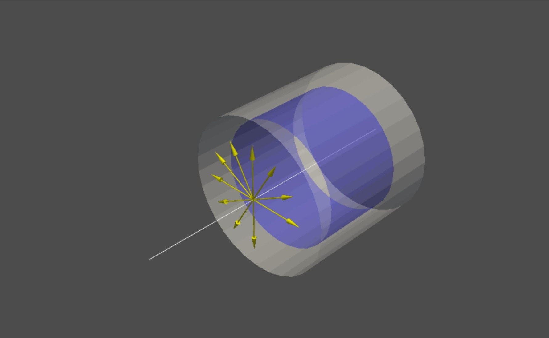
[IM Representation of tube along with raycast]
Connection to the Output Model
As a final step, by using the connection sweeping approach, we trimmed the iso-surface to the dimensions and position of the generated tubes. Additionally we created intermediate circles to which both the iso-surface and tube were attached (in some places, the addition of closing rings/disks was required to make the final model tight (in the sense of a mesh, which was a prerequisite for 3D printing to be possible). The algorithm with connection sweeping involved several sites. It required the use of an intermediate, closing disk at the junction of the envelope and tube. The very end of the vessel and tube also had to be closed with such a disk, then the envelope and end had to be connected to the output 3D model in the same way.
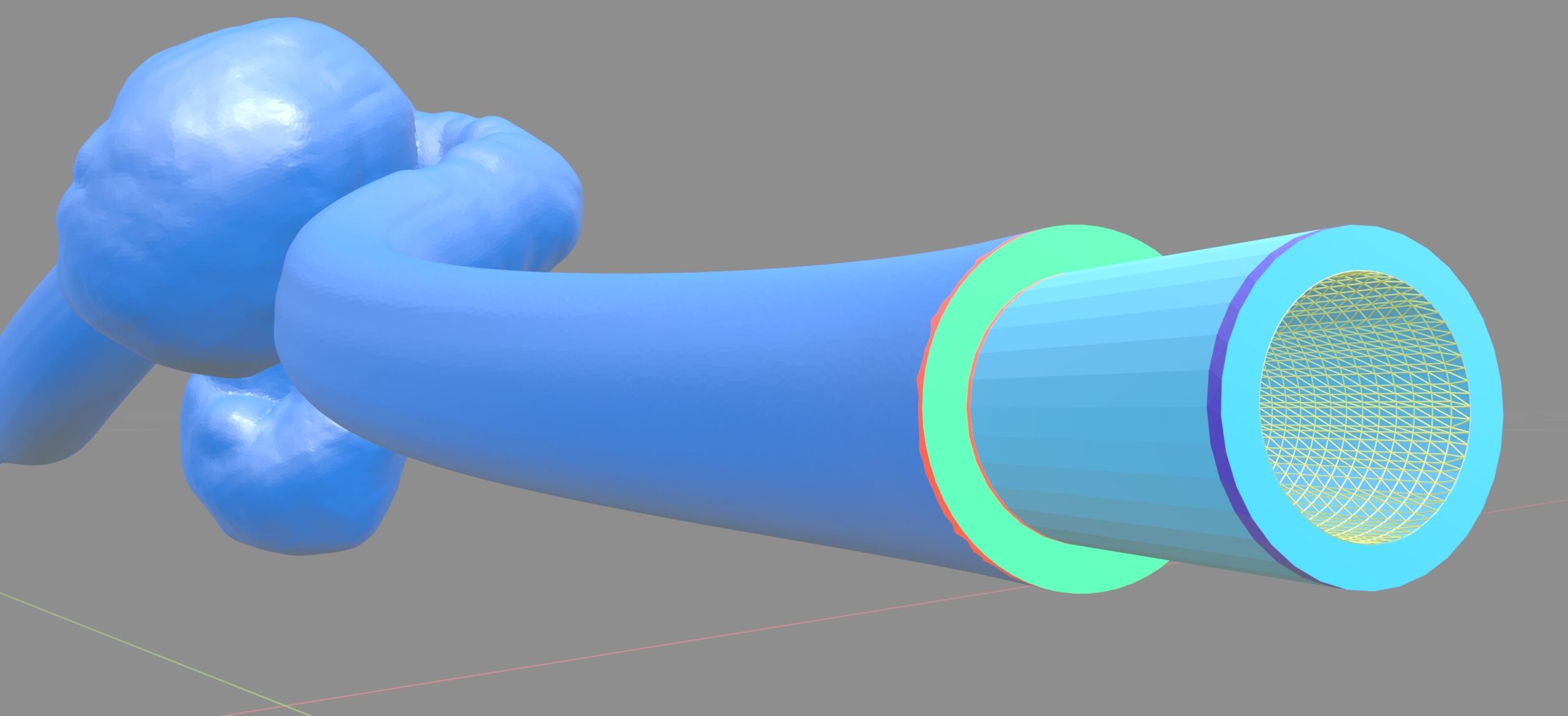
[IM Attached end with coloured parts — offset/bridge/external tube/internal model]
3D printable models: summary
The task of generating an envelope, i.e., an equidistant mesh from the output model, along with matching the connections to the simulator, was a really interesting challenge. We were able to automate a very difficult process. It was previously carried out with sophisticated solutions, software and CAD tools, and required a skilled technician. Using the existing tools created within Graylight Imaging, or extending them, it was possible to generate the pre-set model with great precision and assumed accuracy. Of course, there is still room for improvement in this field. For example, in order to make connections more flexible, especially when two branches are close to each other, but the created toolkit allows for that improvement.